
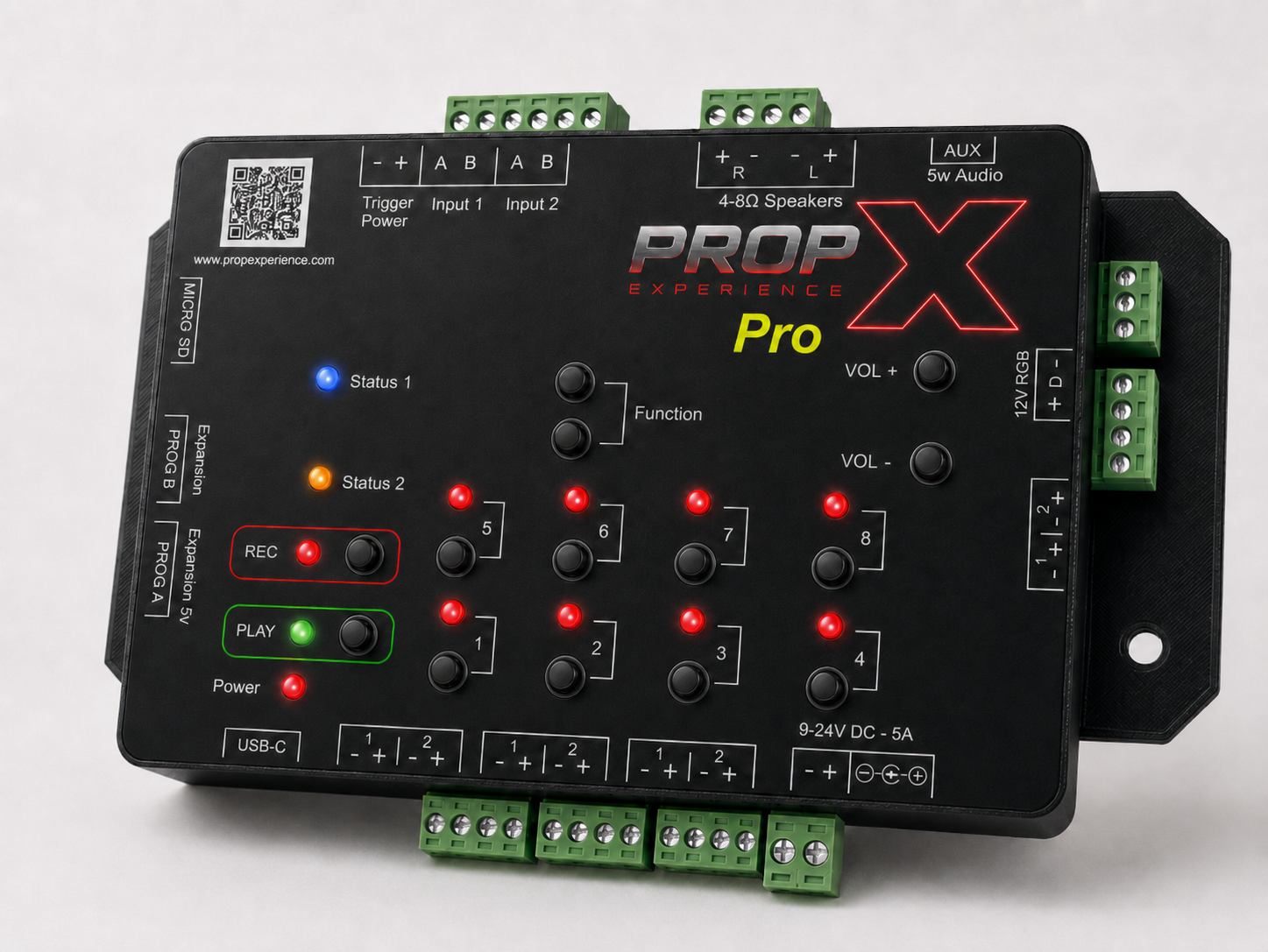
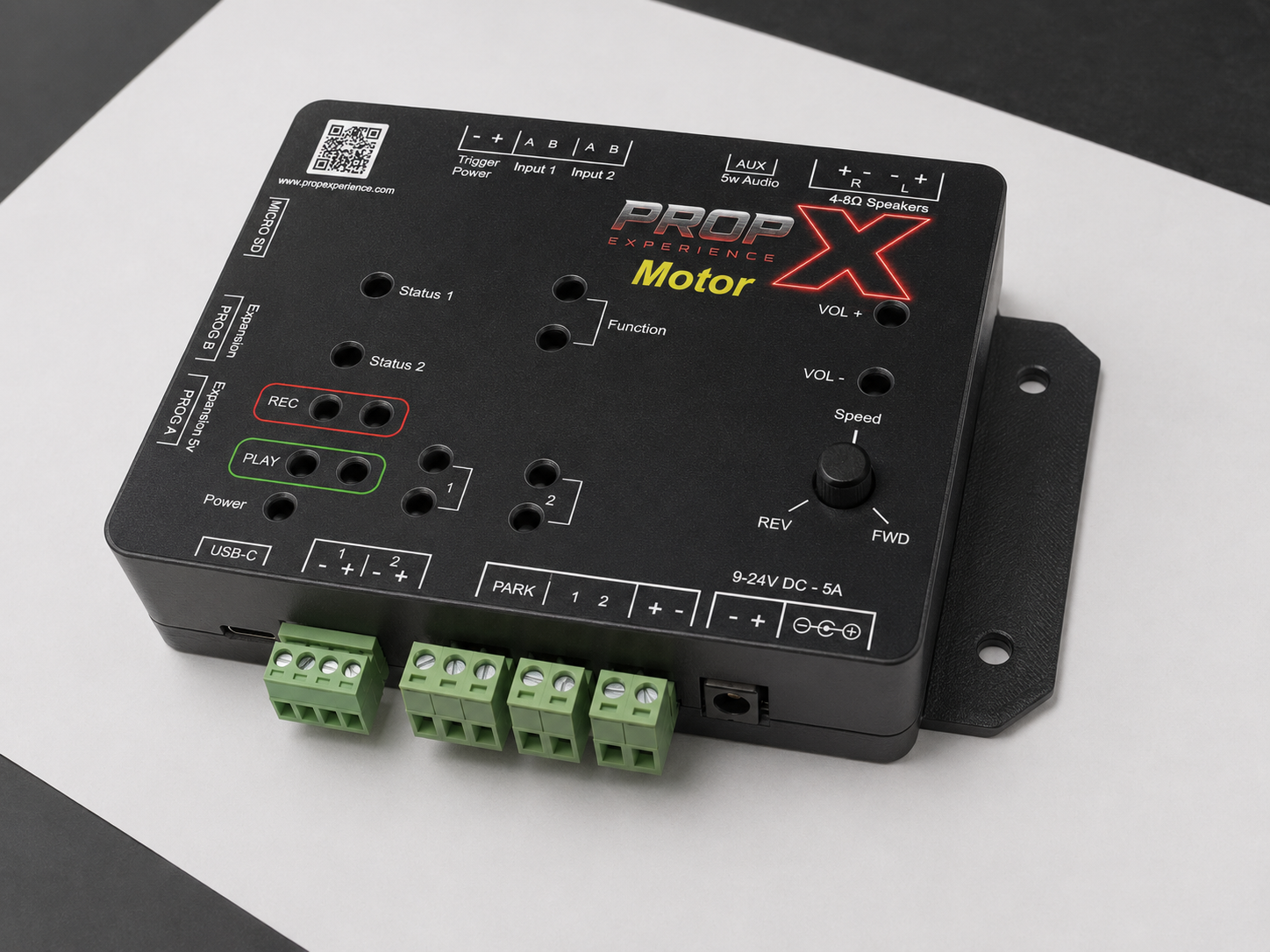
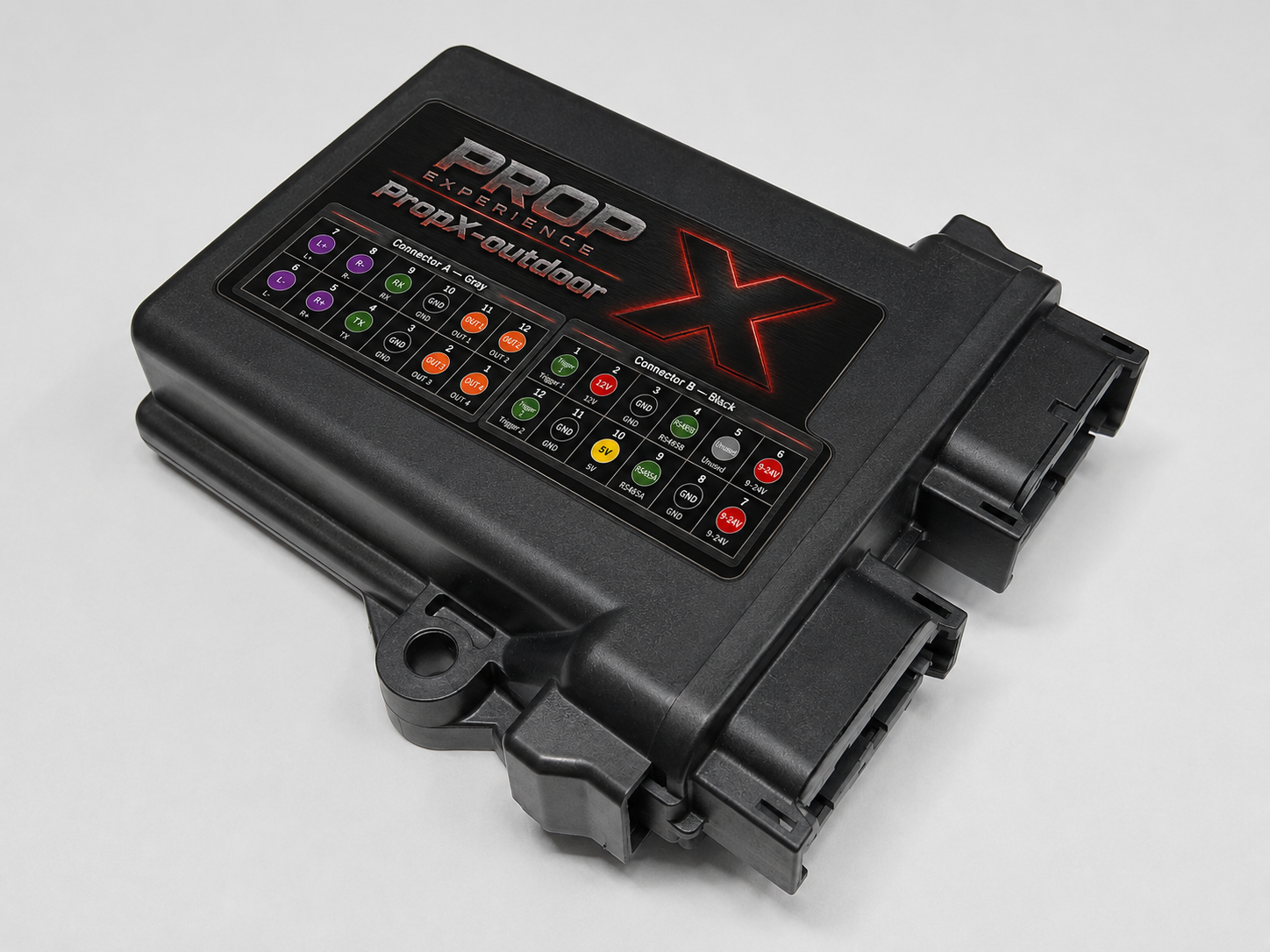
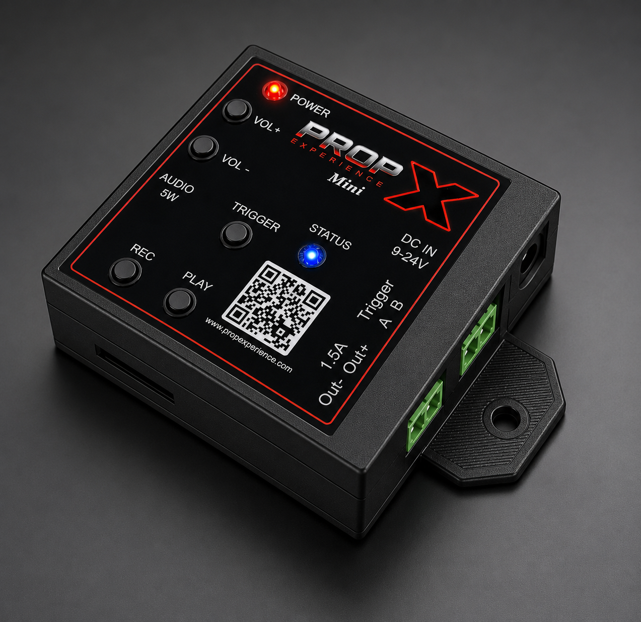
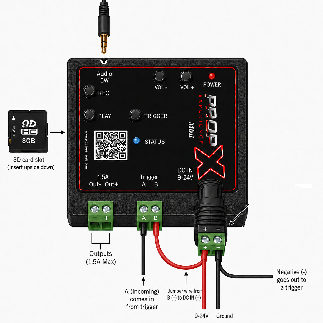
The map of your controller. The hookup diagram below shows the face and every connection: power, the output, the trigger, audio, and the SD card slot.
Power
9–24 V DC into the DC IN jack on the connector edge; the barrel jack's screw-terminal adapter takes bare + and − wires. This supply powers the output — a 9–24 V supply on DC IN is required to fire a prop. The USB-C port on the right-hand side powers the audio section only; it will not run the output. Reverse-polarity protected; no fuse (built-in protection). The barrel adapter is a removable part — see Connectors and spare parts.
Out1 — the output
One switching output, up to 1.5 A. The Mini switches the − side (low-side): your prop's + goes to your supply's +, and the output completes the − side when it turns on.
⚠️ Warning: Never connect a prop drawing more than 1.5 amps.
The green terminal plug pulls off for bench wiring — see Connectors and spare parts.
Trigger — the input
One terminal-block input for a motion sensor, mat, or button; up to 2 A. Wiring (see the diagram above): the trigger's signal wire comes in on A, a jumper wire links B (+) to DC IN (+), and the supply's negative runs out to the trigger.
Audio
A 5-watt output for a small speaker or headphones on the 3.5 mm jack on the top edge — MP3 sound for your prop. Your sound files live on the SD card: the slot is on the side of the case, and the card goes in upside down. Name your show's sound
trigger1.mp3; addambient_default.mp3for a background loop that plays while the prop is idle.Lights — POWER and STATUS
POWER = has power. STATUS = the state at a glance (solid blue = ready); the full table is on the troubleshooting page. *(Firmware drives two status lights; the single-window mapping is being finalized —
#102.)*
QR code
Scan for the online documentation.
Mounting flange
Footprint 2.5" × 2.5". No display, no DMX/Mesh/LED-strip ports on this model.
Connectors and spare parts
The Mini's power and signal connections use removable plug-in parts — wire them on the bench, and swap a damaged one without resoldering.
Plug-in screw terminals — the green two-pin blocks for Out1 and Trigger. Strip the wire, clamp it under the screw, and push the block onto its header.
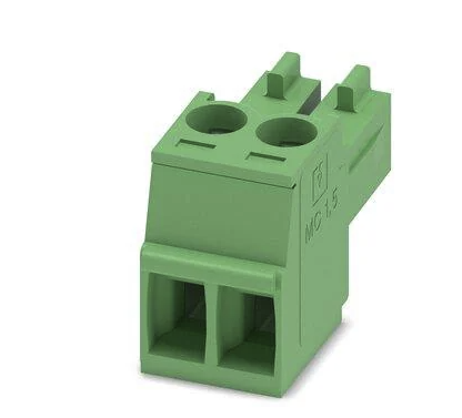
Need a spare? Order the screw terminals on Amazon.
DC barrel connector — screws onto your 9–24 V supply's bare + / − wires and plugs into the DC IN jack.
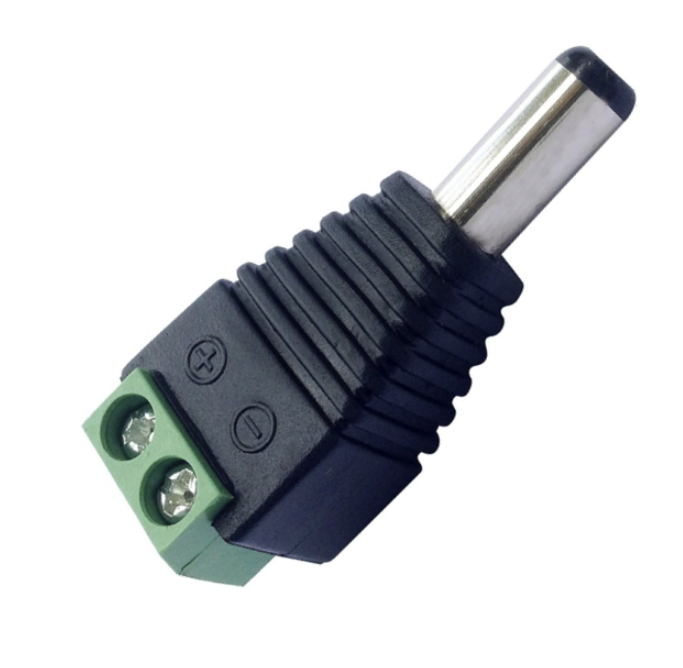
Need a spare? Order the barrel connector on Amazon.