
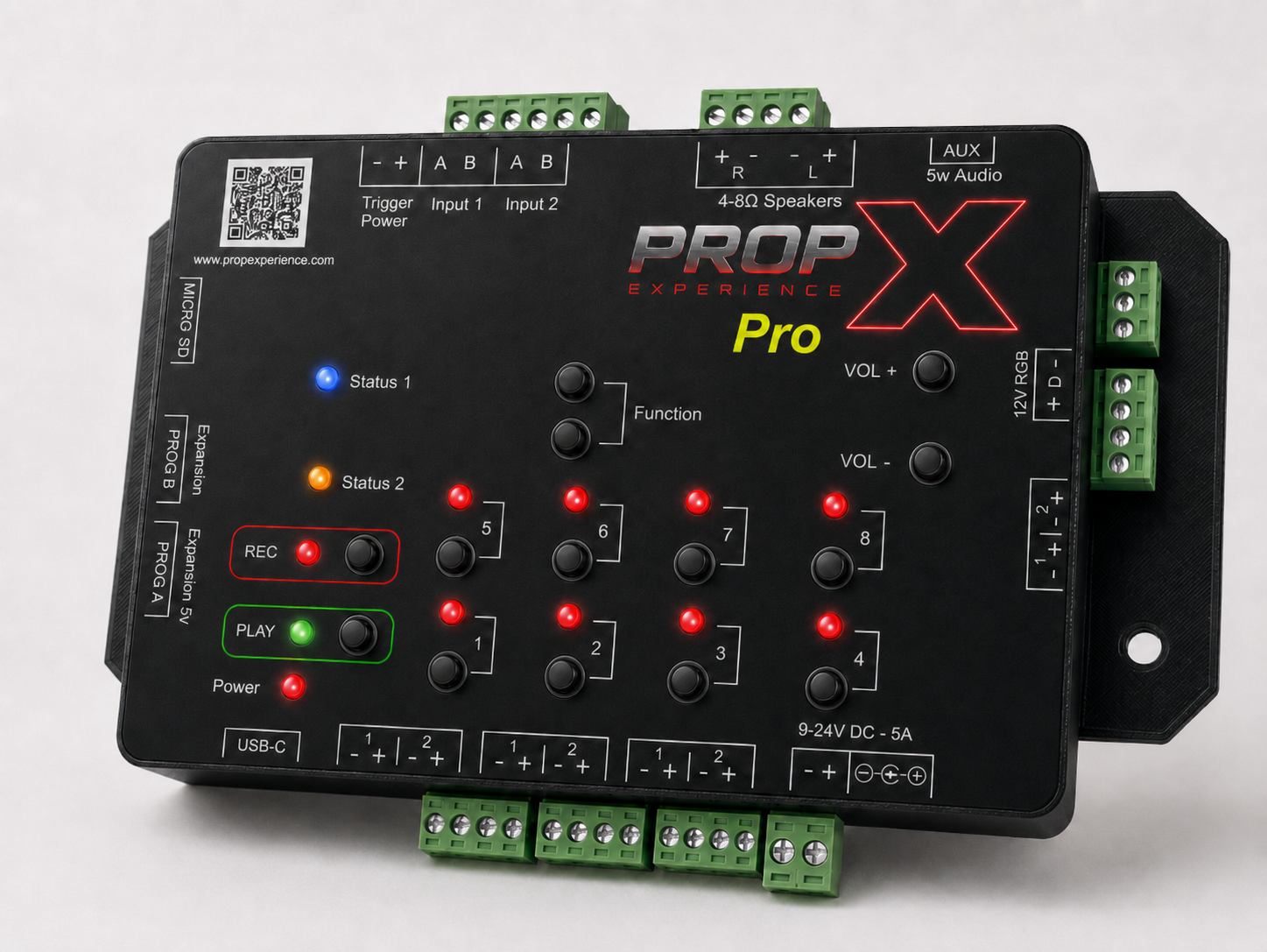
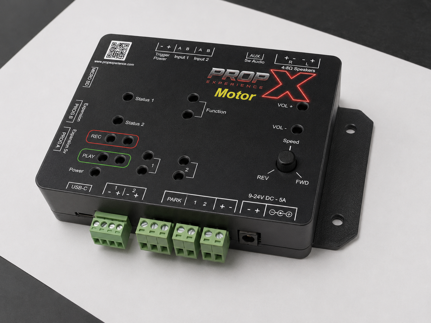
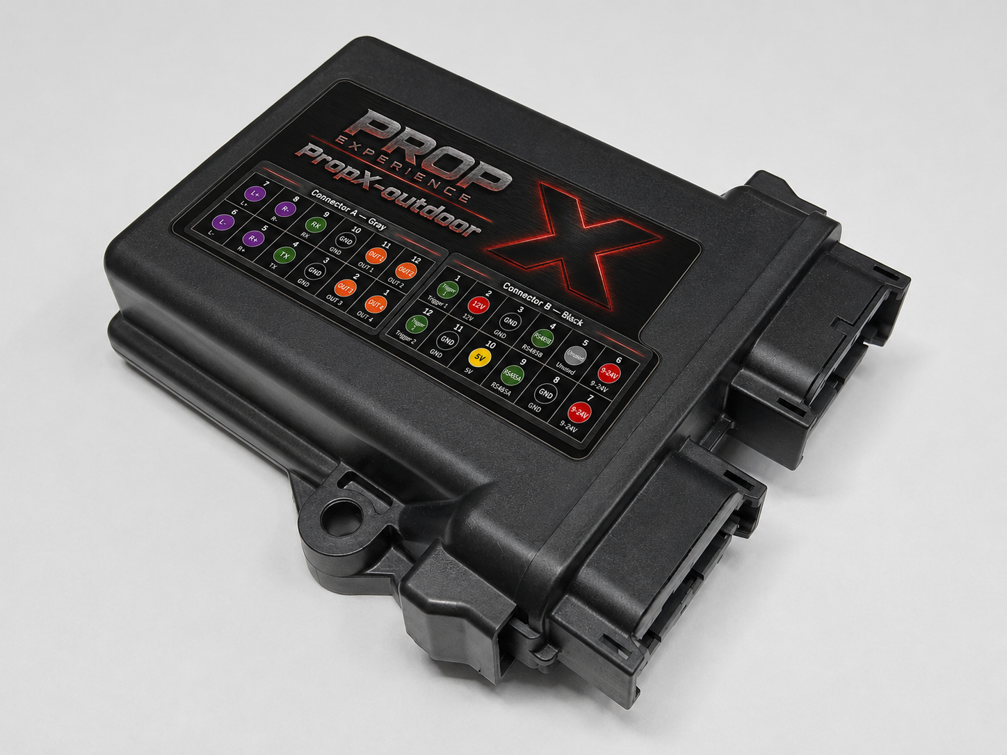
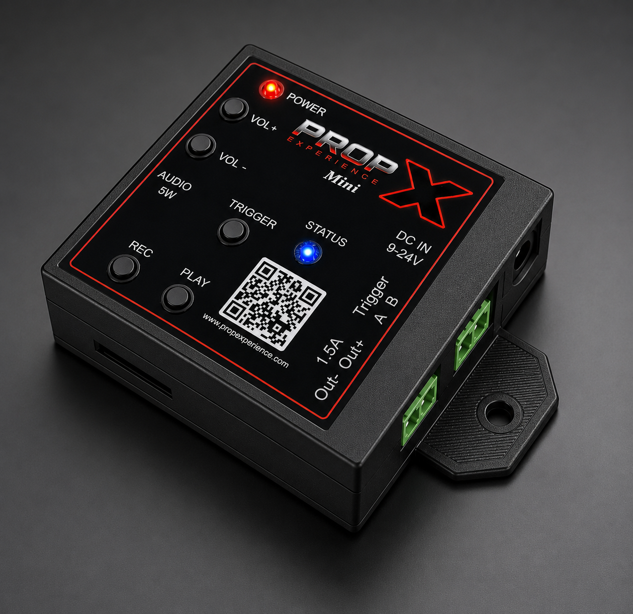
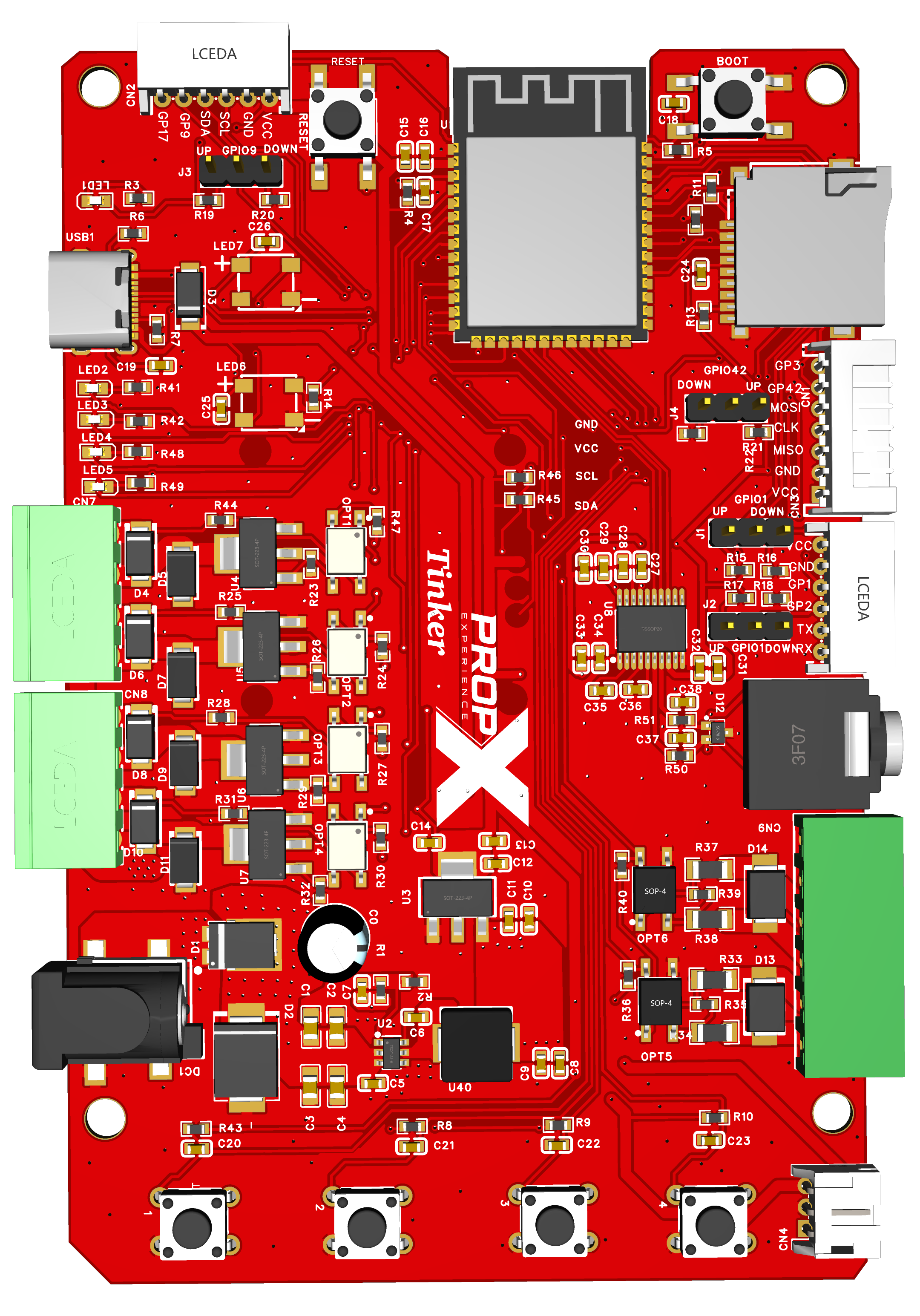
From bare board to a wired, sounding, command-driven I/O machine.
Before you start, you’ll need
- Your Tinker board, standoffs, and a non-metal surface
- A USB-C data cable; VS Code + PlatformIO on your computer
- A 9–24 V DC supply (only when wiring real loads)
- Loads, switches/sensors, powered speakers, a FAT32 MicroSD card with MP3s
- Optional: the OLED module, I²C/SPI/serial add-ons
- Time: 30–60 minutes
⚠️ Warning — two power worlds: USB-C powers the 3.3 V logic; the 9–24 V supply powers loads only. The GPIO pins are 3.3 V only and not 5 V tolerant — high voltage must only meet the board through the output connectors and isolated inputs.
Mount on standoffs
A bare board on anything conductive can short and die at power-on. Standoffs, non-metal surface, dry and indoors.
Flash the firmware
Open the repo folder in VS Code, connect USB-C, run pio run -t upload -t monitor → banner + > prompt. Full toolchain walkthrough: the repo's getting started guide.
Wire a load
Unplug USB-C AND the load supply first. Wire the load between Connector D's 12 V pin and an OUT pin (the output completes the ground side). Add a flyback diode across motors, solenoids, and relays.
Reconnect the load supply (entry point/jack role — #95), then USB-C: the load stays OFF at boot by design. Output console commands are being finalized with the board (#99 — the repo's docs are the live reference); the outputs switch ON when their GPIO is driven LOW.
Wire a switch or sensor
One input pair of the isolated input connector, either polarity; the field-side +12 V/GND pins feed the sensor side as needed.
Sound
FAT32 card in, powered speakers or headphones in the jack, box then play 1. Volume: vol 1–vol 20.
Add the display (optional)
Everything unpowered; OLED module onto the display header matching VCC/GND/SDA/SCL; power up → PropX logo at boot.
Build outward (makers)
Serial on A, I²C on B (addresses mustn't clash with the display), SPI on C (use GPIO3/42 as your chip-select — the bus is shared with the MicroSD card), power from the 5 V/3.3 V tap (limits — #98). Set jumpers J1–J4 for any breakout pin used as an input; GPIO3/17 need gpio <pin> up/down instead.
Make it yours
The firmware is one file (src/main.cpp). Edit, pio run -t upload, done. Keep the repo's hardware reference beside you when wiring.