
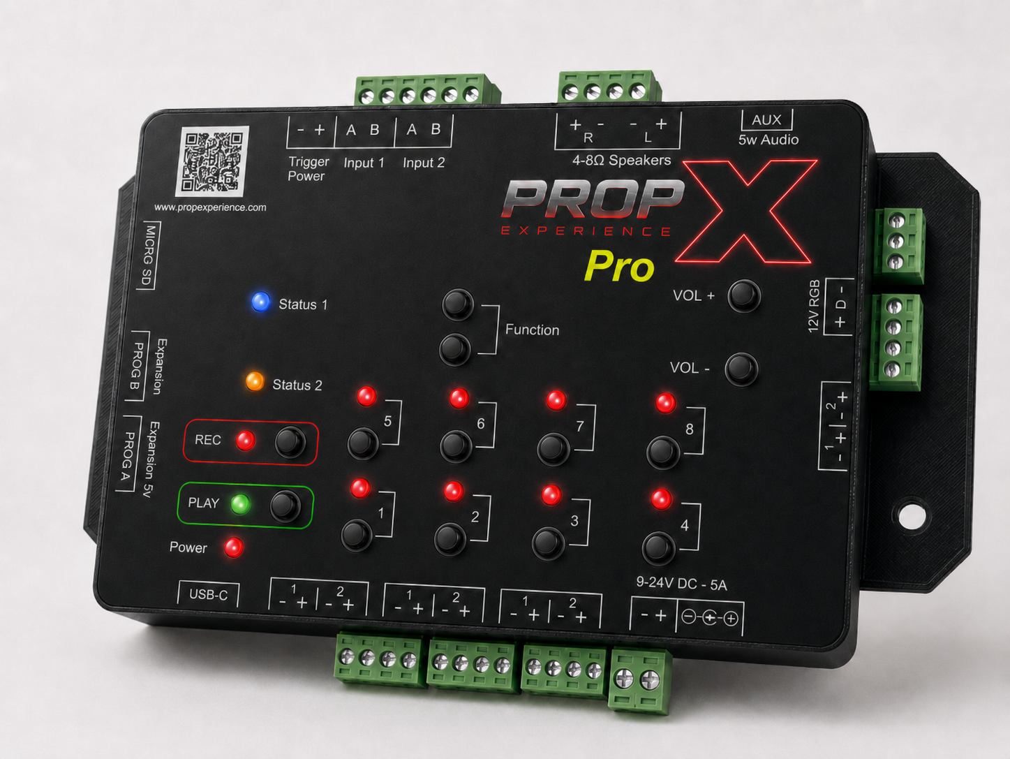
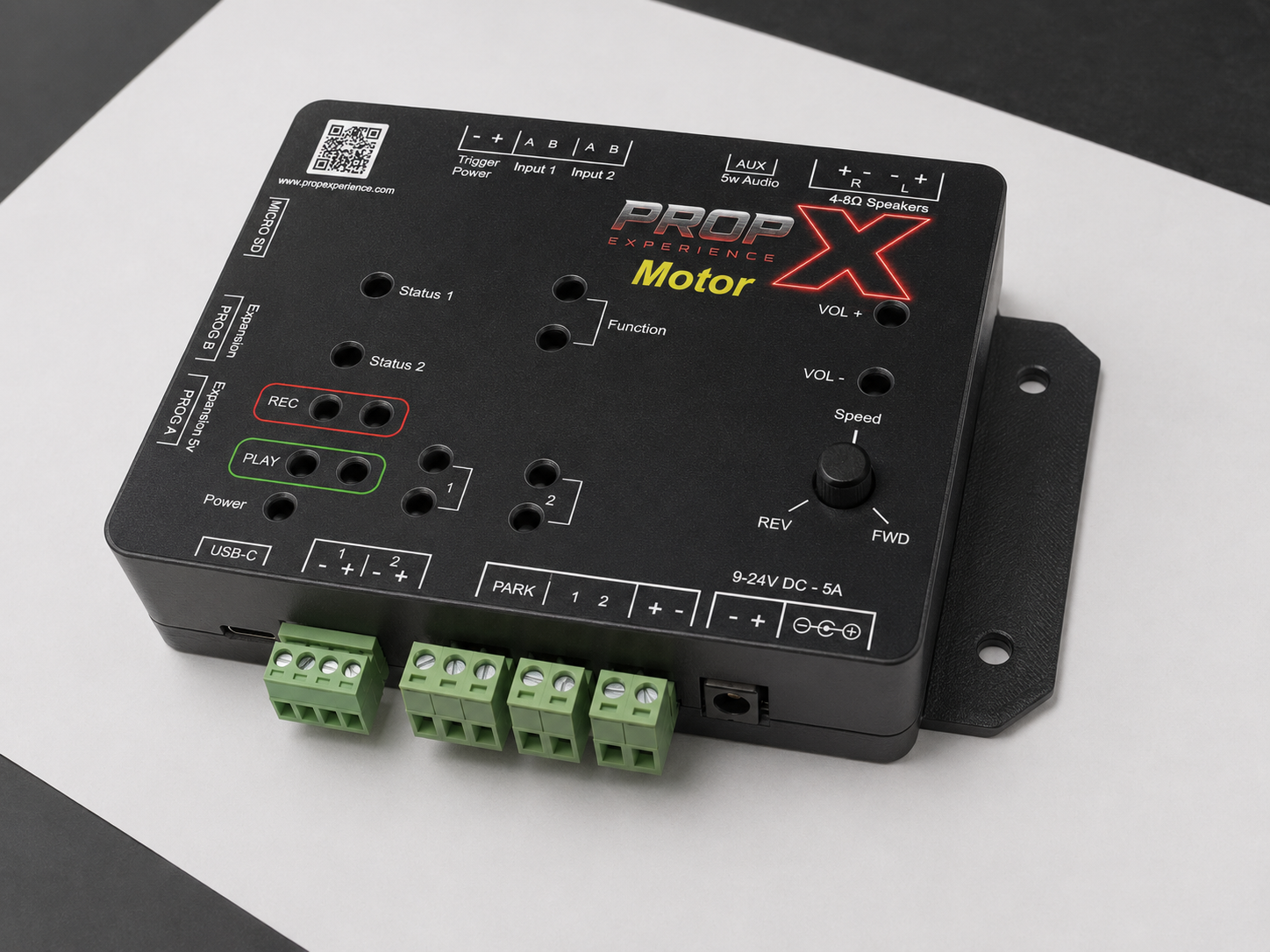
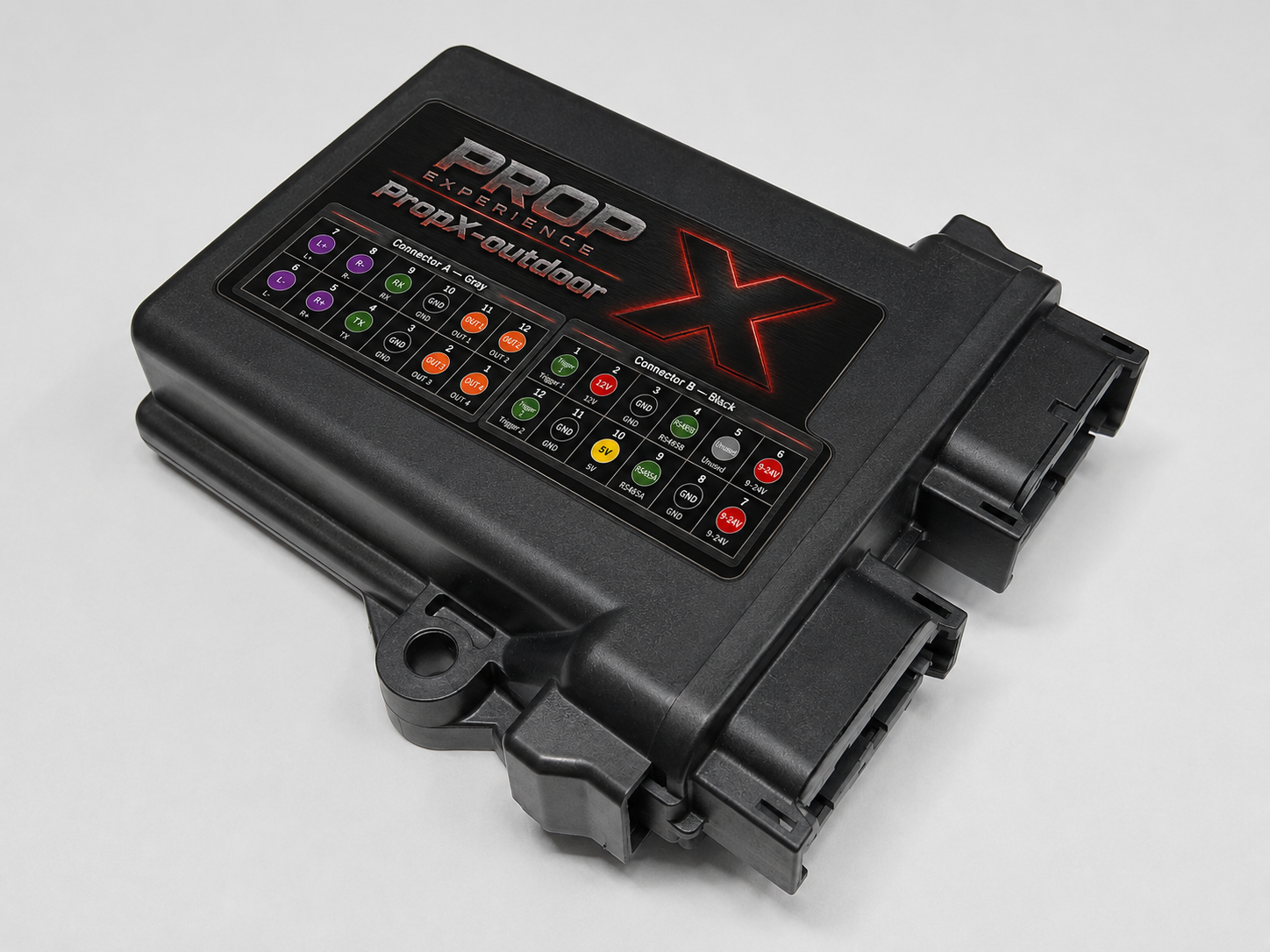
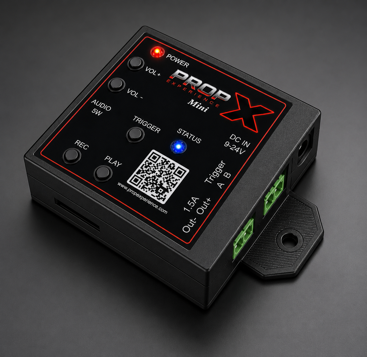
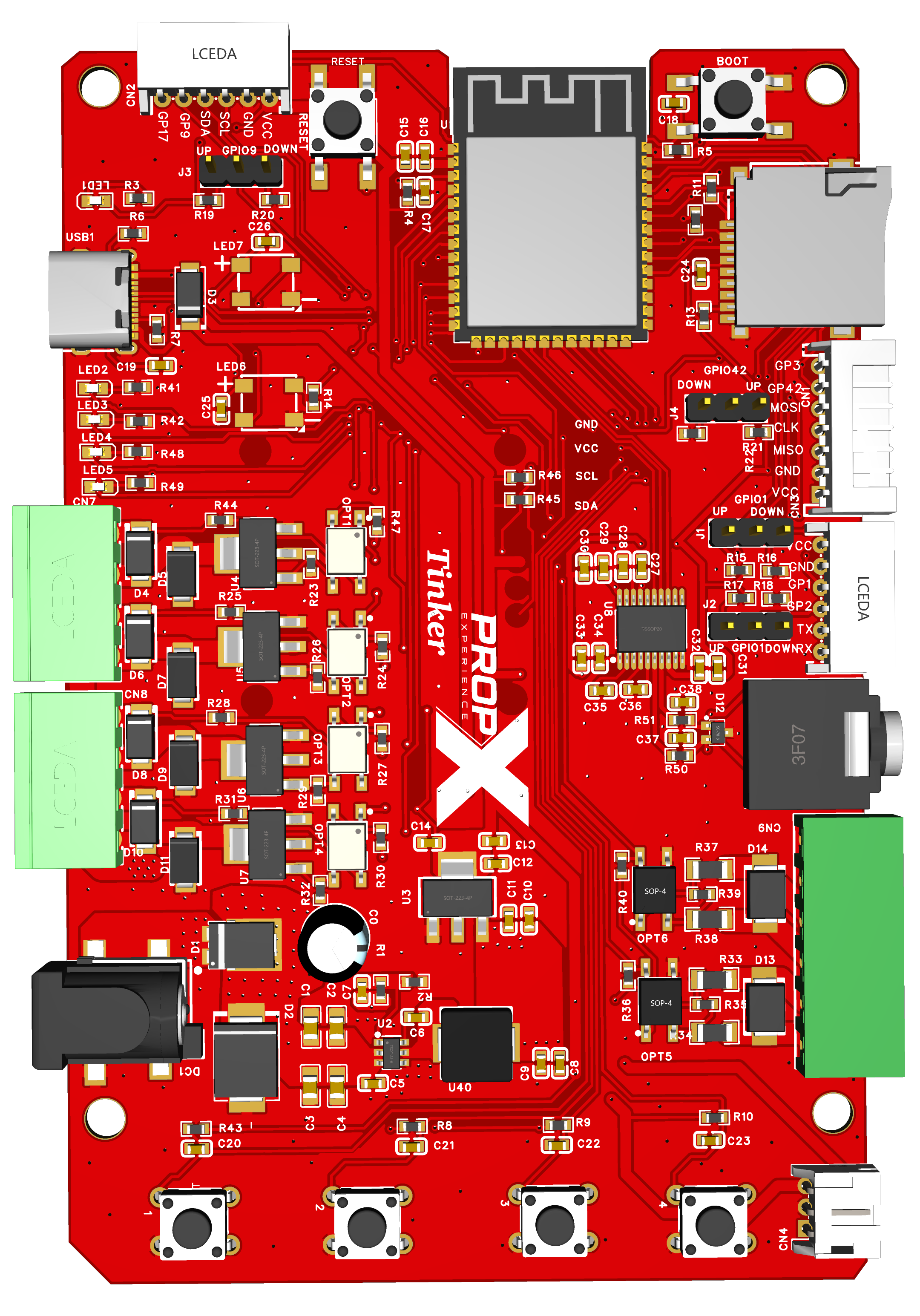
The friendly map. The deep, pin-by-pin version is the repo's hardware reference — the single source of truth for every pin.
USB-C
Powers the board (5 V → 3.3 V logic), loads firmware, and carries the serial console. One cable, three jobs.
Load power (barrel jack)
A separate 9–24 V supply for your loads only — it feeds the output connectors and the isolated inputs, never the logic. (The jack's "9-12V" marking is being corrected to 9–24 V; its role in the power path is being documented — #95.)
Output connectors D and E
Four opto-isolated, active-LOW, low-side MOSFET outputs (two per connector). Wire each load between the 12 V pin and an OUT pin — outputs stay safely OFF while the board resets or sits unprogrammed.
⚠️ Warning: Keep loads under 1.5 A each (rating — #98); add a flyback diode across motors, solenoids, and relays.
Isolated inputs
Two optocoupler inputs — sense switches and signals living on the load-power world with no electrical connection to the logic. Either polarity works.
Audio jack
3.5 mm line-level output — powered speakers, headphones, or an amp; a bare speaker won't work. (The "5w" silkscreen is being reconciled — #96.)
MicroSD card slot
FAT32 card with MP3s, played from the console's
boxbrowser.Display header
For the optional SSD1306 OLED (I²C, 0x3C) — the firmware draws the PropX logo at boot. Shares the I²C bus with Connector B.
Breakout connectors A, B, C
Serial (A: TX/RX), I²C (B: SDA/SCL + two GPIO), SPI (C: MOSI/CLK/MISO + two GPIO) — all 3.3 V only. GPIO3 and GPIO17 have no pull resistor; configure one before trusting them as inputs.
Jumpers J1–J4
Set a breakout pin's resting level: shunt toward VCC = pull-up, toward GND = pull-down, removed = floating.
Power tap ("5v output")
5 V + 3.3 V + GND for your add-ons (current limits — #98).